Why Connector Mis-Mating Happens in Multi-Connector Systems
Modern equipment can contain dozens of electrical connections within a relatively small area. Heavy equipment, agricultural machinery, fleet vehicles, marine systems, and industrial equipment may all use several similar connectors within the same wiring harness or control area.
That creates a practical design challenge.
Two connectors may use similar housings, contain the same number of circuits, or sit close enough together that one harness branch can physically reach more than one mating location.
During original assembly, the intended connection may be obvious. Field service is different. Years later, a technician may be troubleshooting equipment in poor lighting, working around contamination, wearing gloves, or reconnecting multiple harness branches after a repair.
If similar connectors can physically reach and mate with one another, relying entirely on memory or labels increases the opportunity for an incorrect connection.
Depending on the circuits involved, connector mis-mating may cause:
• A nonfunctioning circuit
• Incorrect sensor or control signals
• Additional troubleshooting
• Equipment faults
• Increased service time and downtime
The consequences depend on the system, so engineers should evaluate the risk during design rather than assume every incorrect connection produces the same result.
For systems containing multiple similar interfaces, mis-mating prevention should be considered part of the overall harness architecture.
How to Diagnose Wiring vs Connector Problems in Vehicles
What Are Keyed Electrical Connectors?
A keyed electrical connector uses physical features in the mating interface to differentiate one connector configuration from another.
Compatible plug and receptacle configurations are designed to mate. An incompatible key configuration uses a different physical interface that helps prevent the wrong connector pair from being fully connected.
This creates a physical layer of error prevention instead of relying only on visual identification.
Within the DEUTSCH DT family, for example, different key configurations are available for certain housings. CCK currently lists DT products identified with specific key arrangements, including an 8-way and 12-way B-key enhanced-seal assembly.
The important point is that visual similarity does not determine compatibility.
Two connector housings may appear nearly identical while using different mating configurations. Likewise, different colors should not automatically be assumed to make two connectors mechanically incompatible.
Engineering Note: Always verify connector keying and mating compatibility using the exact manufacturer part numbers and published documentation. Do not determine compatibility by appearance or color alone.
Keying vs. Retention: What Does Each Feature Actually Do?
One source of confusion is that several connector features contribute to reliability, but they do not all solve the same problem.
|
Connector Feature |
Primary Purpose |
|
Mechanical keying |
Helps prevent incompatible connector housings from mating |
|
Wedgelock / secondary lock |
Helps retain contacts correctly inside the housing, may include keying features |
|
Latch or mating mechanism |
Helps keep the two connector halves engaged |
|
Visual identification |
Helps assemblers and technicians identify circuits |
|
Harness routing |
Helps limit which mating locations a connector can physically reach |
This distinction is particularly important when discussing wedgelocks.
A wedgelock supports contact retention. Mechanical keying addresses the compatibility of the connector housings themselves.
Both improve system reliability, but they address different failure modes.
Keying Is Only One Way to Prevent Connector Mismatch
Mechanical keying is one of the strongest ways to reduce accidental cross-connection, but reliable systems often use more than one prevention method.
|
Mis-Mating Prevention Method |
What It Helps Prevent |
Best Used For |
|
Mechanical keying |
Incompatible connectors being physically mated |
Similar connectors located close together |
|
Different connector configurations |
Cross-connection between harness branches |
Systems with several interfaces |
|
Harness routing |
A connector reaching an incorrect mating point |
Dense wiring harnesses |
|
Visual identification |
Assembly and technician errors |
Production and field service |
|
Clear labeling |
Incorrect reconnection during maintenance |
Frequently serviced equipment |
These approaches are complementary.
For example, mechanical keying can provide physical error prevention, while labels help technicians quickly identify the intended circuit. Harness routing provides another layer by limiting which connector locations a branch can reasonably reach.
That layered strategy makes a multi-connector system easier to understand and harder to reconnect incorrectly.
How Connector Housing Configuration Helps Prevent Mis-Mating
Not every interface within a multi-connector wiring harness needs to use the exact same connector configuration.
Where electrical and mechanical requirements allow, system designers may differentiate interfaces through:
• Connector family
• Cavity count
• Housing configuration
• Mating interface
• Manufacturer-supported keying options
The goal is not to introduce unnecessary variation. Standardization is valuable because it can simplify inventory, tooling, assembly, and field service.
Instead, engineers should identify locations where identical or compatible interfaces create a meaningful risk of cross-connection and determine whether physical differentiation is justified.
Electrical requirements still come first.
Connector selection needs to account for:
• Number of circuits
• Current requirements
• Wire gauge
• Contact size
• Environmental sealing
• Operating environment
• Service requirements
For example, within the DT family, DTM, DT, and DTP connectors use different contact systems for different electrical requirements. Those families should therefore be selected based on the circuit and application—not simply to make connectors look different.
DT vs DTM vs DTP Connectors: Differences in Contact Size, Amp Rating, and Application
Do Wedgelocks Prevent Connector Mis-Mating?
Not primarily.
A wedgelock is a secondary locking component used to help secure contacts in their intended position inside applicable connector housings.
Correct contact retention helps prevent terminal movement or back-out, particularly in vibration-heavy environments.
Connector keying, by contrast, addresses whether two connector housings are intended to mate.
A useful distinction is:
Keying helps determine which connector housings can mate.
Wedgelocks help keep contacts correctly retained inside those housings.
CCK's DT assembly kits include the mating housings, corresponding plug and receptacle wedgelocks, and the appropriate contacts needed to build the assembly. For example, CCK's current 2-way and 4-way DT kits include both connector halves, both wedgelocks, and Size 16 pins and sockets.
How Wedgelocks Prevent Connector Failure in Harsh Environments
When Mechanical Keying Alone Is Not Enough
Mechanical keying can prevent incompatible connector pairs from mating, but it does not solve every potential service or assembly error.
A complex harness may still contain multiple connectors using the same valid key configuration. A technician may also need to identify which connector belongs to which circuit even when incorrect housings cannot mate.
That is why keying works best as part of a broader design strategy.
Engineers should consider combining keying with:
Harness routing: Design branch lengths and breakout locations so a connector naturally reaches its intended component.
Clear identification: Use durable labels or circuit identification to make servicing more intuitive.
Connector configuration planning: Avoid creating unnecessary groups of identical, interchangeable interfaces in the same service area when the application permits differentiation.
Service documentation: Make sure technicians can identify mating pairs without relying solely on memory.
The objective is not to make a wiring harness impossible to service. It is to make the correct connection intuitive and an incorrect connection difficult.
Harness Routing Can Reduce Connector Mis-Mating
One of the most effective prevention strategies does not require changing the connector at all.
It involves the physical architecture of the harness.
Consider two identical connectors positioned several inches apart. If both harness branches have enough excess length to reach either component, the design creates an opportunity for cross-connection.
If branch lengths, breakout positions, and component locations are designed so each connector naturally reaches its intended interface, the harness itself adds another layer of error prevention.
Important design considerations include:
Branch Length
Avoid unnecessary excess length that allows a branch to reach unrelated interfaces.
Breakout Location
Position harness breakouts so individual branches naturally route toward their intended components.
Connector Placement
Consider whether multiple similar mating points are located unnecessarily close together.
Service Access
The correct connection should remain identifiable after surrounding components are installed.
Harness routing should never create excessive wire tension simply to prevent mis-mating. The goal is thoughtful physical differentiation without introducing new reliability problems.
Real-World Example: Two Similar DT Connectors During Field Service
Consider a piece of off-road equipment with two similar multi-pin DT connectors located near the same control assembly.
During a field repair, both connectors are disconnected. Each harness branch has enough length to reach either mating point.
If both interfaces use identical compatible configurations, the technician may have to depend on labeling or service documentation to determine which branch belongs where.
A stronger design could combine several approaches:
• Use manufacturer-supported keying differences where appropriate.
• Route each harness branch toward its intended component.
• Keep excess branch length controlled.
• Add durable circuit identification.
• Use the correct wedgelocks and contacts to maintain contact retention after reconnection.
The solution is not simply "use a keyed connector."
The solution is to design the entire connection system so the intended mating relationship remains clear during both assembly and future service.
That system-level approach is especially valuable in heavy equipment, where downtime is often driven as much by troubleshooting difficulty as by the original electrical fault.
Designing Connector Identification for Field Service
A connector system should be easy to assemble correctly at the factory and easy to reconnect correctly years later.
That changes how engineers should think about connector identification.
Technicians servicing heavy equipment may be working around oil, dust, vibration damage, weather exposure, or limited visibility. Several connectors may already be disconnected before troubleshooting begins.
Visual identification can help through:
• Durable circuit labels
• Harness identification
• Consistent connector naming
• Clear service documentation
• Visual differentiation where appropriate
However, identification should generally be another layer of protection—not a replacement for physical error-proofing where an incorrect connection creates significant risk.
A useful design question is:
Could a technician unfamiliar with the original assembly disconnect this harness and confidently reconnect it correctly in the field?
If the answer is no, the system may benefit from additional keying, routing, or identification controls.
Why the Right Tools Matter for Installing and Removing Automotive Connectors
A Practical Connector Mis-Mating Prevention Framework
Engineers evaluating a multi-connector system can use a straightforward six-step process.
Step 1: Identify Similar Interfaces
Locate connectors that could realistically be confused because of similar housings, cavity counts, locations, or overlapping harness reach.
Step 2: Evaluate the Consequence of Incorrect Mating
Determine what would happen if an incorrect connection were made. The greater the operational consequence, the stronger the case for physical error prevention.
Step 3: Evaluate Keyed Connectors and Housing Differentiation
Review manufacturer-supported connector keying options and compatible configurations.
Step 4: Control Harness Reach
Evaluate whether branch length or routing unnecessarily allows one connector to reach an unrelated interface.
Step 5: Add Identification
Use durable labeling or circuit identification to support both assembly and field service.
Step 6: Review the System From the Technician's Perspective
Ask whether someone unfamiliar with the original assembly could confidently reconnect the system under real service conditions.
This process treats preventing connector mismatch as an engineering and serviceability problem rather than simply a labeling problem.
Common Connector Mis-Mating Prevention Mistakes
Relying Only on Color
Color is useful for identification, but it does not necessarily indicate mechanical mating compatibility.
Relying Only on Labels
Labels can become damaged, obscured, or difficult to read under field conditions.
Assuming Similar Connectors Cannot Mate
Verify exact part numbers, key configurations, and manufacturer mating documentation.
Designing for Assembly but Not Field Service
The original assembler may have clean components and detailed drawings. A field technician years later may not.
Designing for both conditions can reduce avoidable troubleshooting and downtime.
Choosing Keyed Connectors for Heavy Equipment and Industrial Systems
Mis-mating prevention is important, but keyed connectors still need to satisfy the primary electrical and environmental requirements of the application.
Before selecting a configuration, verify:
|
Selection Factor |
What to Confirm |
|
Circuit count |
Correct number of required positions |
|
Current requirements |
Appropriate contact and connector capacity |
|
Wire size |
Compatibility with contacts and seals |
|
Environmental exposure |
Moisture, contamination, temperature, vibration |
|
Key configuration |
Correct manufacturer-supported mating pair |
|
Serviceability |
Access for inspection and contact replacement |
|
Tooling |
Correct crimp, insertion, and removal tools |
|
Harness layout |
Routing, reach, and connector location |
Product configuration should be verified at the complete assembly level.
For a DT system, that means confirming the correct:
• Plug housing
• Receptacle housing
• Key designation where applicable
• Cavity count
• Wedgelocks
• Pins and sockets
• Wire gauge/contact compatibility
• Crimp and removal tooling
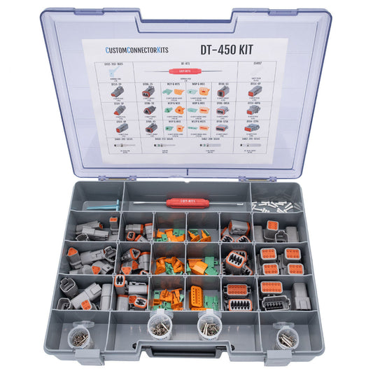
CCK currently offers individual DT assembly kits as well as larger multi-configuration kits. The DT-450 kit, for example, includes multiple DT cavity counts, mating wedgelocks, Size 16 contacts, cavity plugs, and contact-removal tools, with compatible crimp tooling available separately.
This approach can be particularly useful for maintenance operations working across multiple DT configurations because it supports both connector replacement and field service without requiring a completely separate component system for every repair.
Frequently Asked Questions About Keyed Connectors
What is a keyed electrical connector?
A keyed electrical connector uses physical features in its mating interface so that only the intended compatible connector configuration can mate. Keying can help prevent cross-connection when several similar connectors are used within the same electrical system.
How do keyed connectors prevent incorrect connections?
Keyed connectors use mechanical differences between mating configurations. An incompatible key configuration is physically different from the intended mating pair, helping prevent an incorrect connector from being fully connected.
Can two connectors that look the same have different keying?
Yes. Visually similar connector housings may be available in different key configurations. Always verify the exact part number, key designation, and manufacturer compatibility information.
Is connector color coding enough to prevent mis-mating?
Not necessarily. Color coding improves visual identification but does not automatically make two connectors mechanically incompatible. Where incorrect mating creates meaningful risk, combine identification with keying, configuration differences, or controlled harness routing.
Do wedgelocks prevent the wrong connectors from being connected?
Not necessarily. Wedgelocks primarily provide secondary contact retention inside applicable connector housings. They may offer keying features in some cases. Mechanical keying or polarization of the mating interface is the primary mechanism that helps prevent incompatible housings from being connected.
How can you prevent connector mismatch in a wiring harness?
A strong connector mis-mating prevention strategy combines mechanical keying where available, appropriate connector configurations, controlled harness routing, clear identification, and field-service-aware system design.
Key Takeaways
• Keyed connectors use physical mating differences to help prevent incompatible connector pairs from being connected.
• Connector mis-mating should be treated as a system-design issue, not simply a labeling issue.
• Mechanical keying, housing configuration, harness routing, and identification can work together to reduce errors.
• Wedgelocks support contact retention and should not be confused with connector-housing keying.
• Mechanical keying may need to be supplemented with routing and identification in complex multi-connector systems.
• Exact plug, receptacle, key, contact, wedgelock, and tooling compatibility should be verified before selecting a connector assembly.
• Designing for field service can make correct reconnection easier and help reduce avoidable troubleshooting and downtime.
Continue Exploring CCK Technical Resources
For additional connector selection and system-design guidance, see:
• DT vs DTM vs DTP Connectors: How to Choose the Right One
• How Wedgelocks Prevent Connector Failure
• Integrated Latch vs Jackscrew: Connector Mating Mechanisms Explained
• Common Tooling Across Connector Families: How to Simplify Inventory
• Understanding Contact Sizes: 16 vs 20 vs 12
• Why Electrical Connections Fail in Heavy Equipment
• Best Connectors for Off-Road Equipment: How to Choose the Right Solution
Build Connector Systems With Field Service in Mind
Preventing connector mis-mating begins before equipment reaches the field.
Connector selection, mechanical keying, harness routing, circuit identification, contact retention, and service access should be considered together when designing multi-connector electrical systems.
Custom Connector Kits supplies DEUTSCH and Aptiv connector kits, housings, contacts, wedgelocks, removal tools, and crimp tooling for heavy equipment and demanding industrial applications.
When selecting keyed connectors, verify the exact manufacturer configuration and mating components required for your application. Choosing the correct components—and designing the harness so they are difficult to confuse—can improve initial assembly, simplify field service, and help reduce avoidable electrical downtime.